Running Nuxt 3 Behind an nginx Reverse Proxy

April 24, 2022

I was attempting to run Nuxt 3 RC1 in development mode behind a local nginx reverse proxy, but ran into several issues. There are a number of reasons to run a development application server behind a TLS-terminating reverse proxy, including more closely mirroring a production setup, ensuring an application performs correctly when proxied, and gaining HTTPS support to enable use of newer HTTPS-only user-agent APIs.

However, when nginx reverse proxies to the Nuxt server using a configuration like the following, the application will load correctly in the browser but Vite (bundled with Nuxt) will no longer be able connect to its backend websocket server to provide hot module replacement (HMR).

location / {
    proxy_pass http://localhost:3000;
    proxy_set_header X-Real-IP $remote_addr;
    proxy_set_header Host $host;
    proxy_set_header X-Forwarded-For $proxy_add_x_forwarded_for;
}

To fix this, Vite needs to be made aware it’s being reverse proxied, and nginx needs to pass through Vite’s websocket connection.

In the Nuxt config (nuxt.config.ts), add the following Vite config:

vite: {
  server: {
    hmr: {
      protocol: 'wss',
      clientPort: 443,
      path: 'hmr/'
    }
  }
}

Vite will now use the secure websocket protocol over the same HTTPS port as the application, but it will request it at a new, distinct path.

In the nginx config, add a new location directive to match the configured Vite path (/_nuxt is always prepended), have it perform an HTTP Upgrade, and then reverse proxy to Vite’s websocket server, which always listens on port 24678:

location /_nuxt/hmr/ {
    proxy_http_version 1.1;
    proxy_set_header Upgrade $http_upgrade;
    proxy_set_header Connection "Upgrade";
    proxy_pass http://localhost:24678;
}

After restarting the development server and nginx, Nuxt 3 and Vite HMR work great behind nginx, which now handles TLS termination and reverse proxying of HTTP and websocket traffic.

Update 2023-09-28

As of Nuxt 3.7.4, the nuxt.config.ts configuration is unnecessary, though having the following nginx config in place avoids a WebSocket error about the WebSocket host being undefined:

location /_nuxt/ {
    proxy_http_version 1.1;
    proxy_set_header Upgrade $http_upgrade;
    proxy_set_header Connection "upgrade";
    proxy_set_header Host $host;
    proxy_cache_bypass $http_upgrade;
    proxy_pass http://localhost:3000;
}

Note the differences from the above config – the location path dropped hmr/, the Vite HMR port (24678) became the default Nuxt port (3000), and the Host header was also added (but the Host header is likely not critical for this scenario).
Building cen64 on macOS

January 11, 2020

For testing Nintendo 64 homebrew ROMs, cen64 is the most accurate emulator (though it doesn’t run at full speed yet). Here’s how to build it from source on macOS:

  1. Install XQuartz from the official distributed disk image
  2. brew install cmake glew
  3. git clone https://github.com/n64dev/cen64.git
  4. cd cen64
  5. mkdir build
  6. cd build
  7. cmake ..
  8. make

If you’d like to enable cen64’s debug logging, create a debug build when running cmake:

cmake -DCMAKE_BUILD_TYPE=Debug ..

When running cen64 outside of an XQuartz X11 terminal, it may report:

Using NTSC-U PIFROM
create_device: Failed to initialize the VI.
Failed to create a device.

To fix this, you can run it within an XQuartz X11 terminal, or set the DISPLAY environment variable to something like :0 either in your .bashrc file or inline during invocation:

DISPLAY=:0 ./cen64 /path/to/pifdata.bin /path/to/rom.z64

DISPLAY needs to be set because cen64 calls XOpenDisplay with a NULL display name (presumably to default to your DISPLAY environment variable), but if it’s not set, XOpenDisplay returns NULL and cen64 has no display within which to create a window for rendering Nintendo 64 content.

For extremely verbose register-level output, edit CMakeLists.txt and set DEBUG_MMIO_REGISTER_ACCESS to ON. Make sure to remove any cached data in build/ to ensure your changes are reflected, then recompile and re-run.

Update 2024-03-02

Development on cen64 has not progressed in many months and is now considered unmaintained. ares, a cross-platform, open source, multi-system emulator is now regarded as the best emulator for Nintendo 64 development.

BrewBot - Sending Coffee Notifications to Slack

September 16, 2017

At work, we have a coffee machine that serves dozens of people in the building, and it’s difficult to know when to come get fresh coffee. You might arrive when it’s empty and be tasked with making more, but the ideal situation is to arrive just as a fresh pot is being brewed.

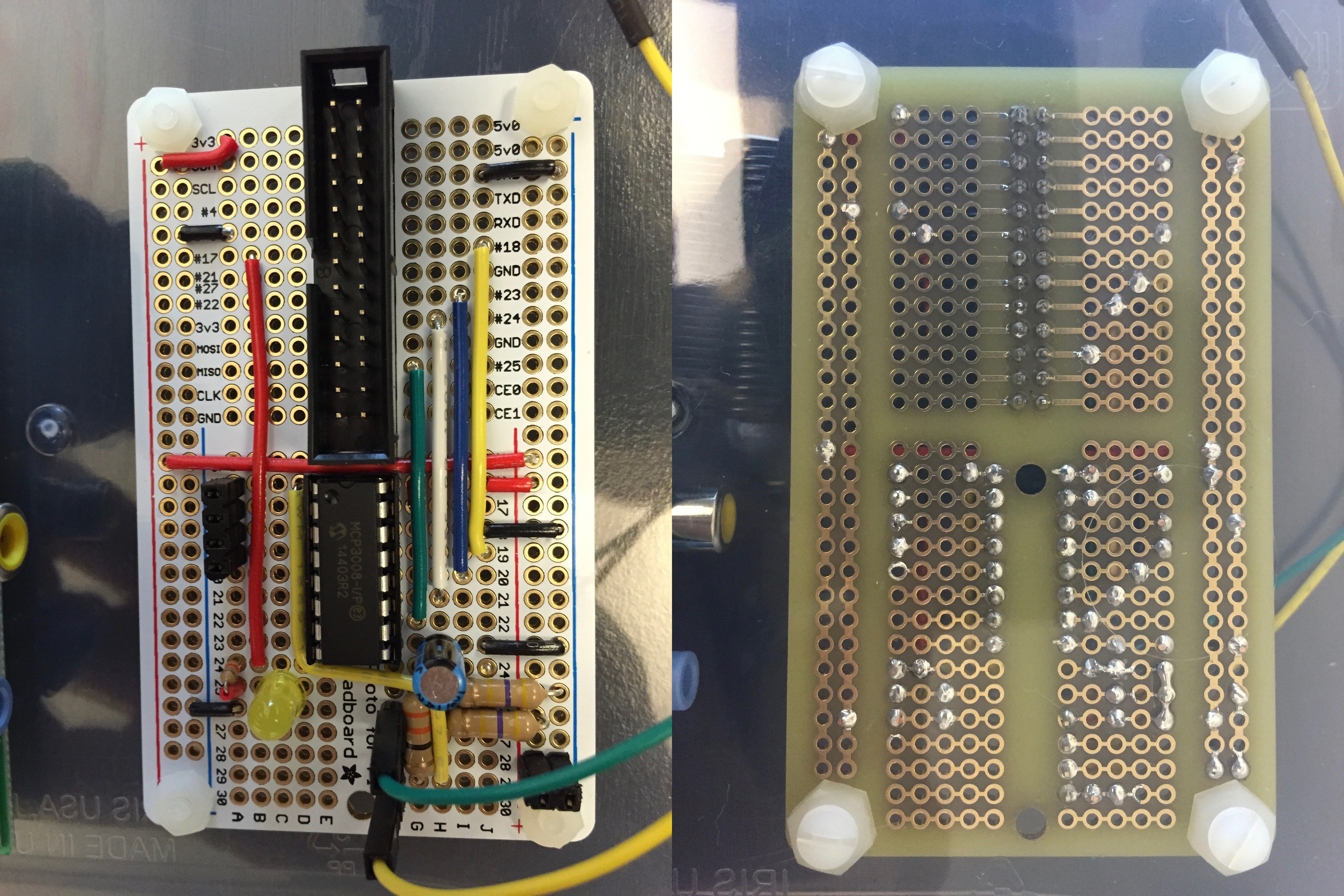
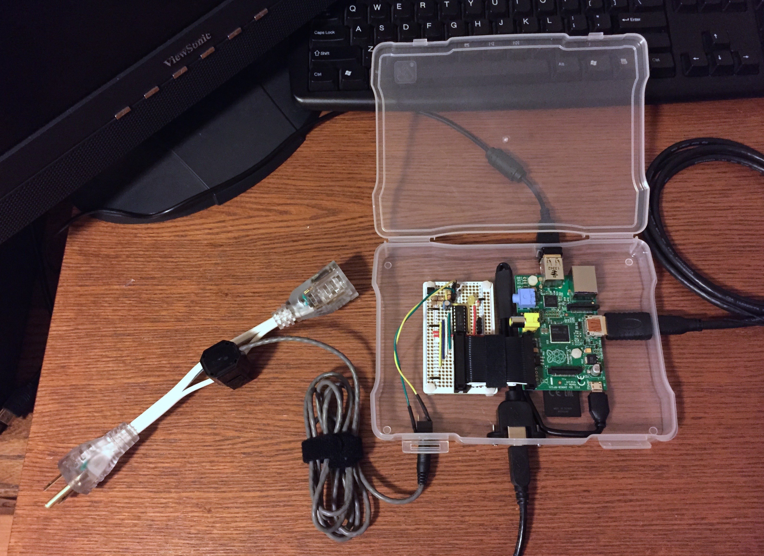
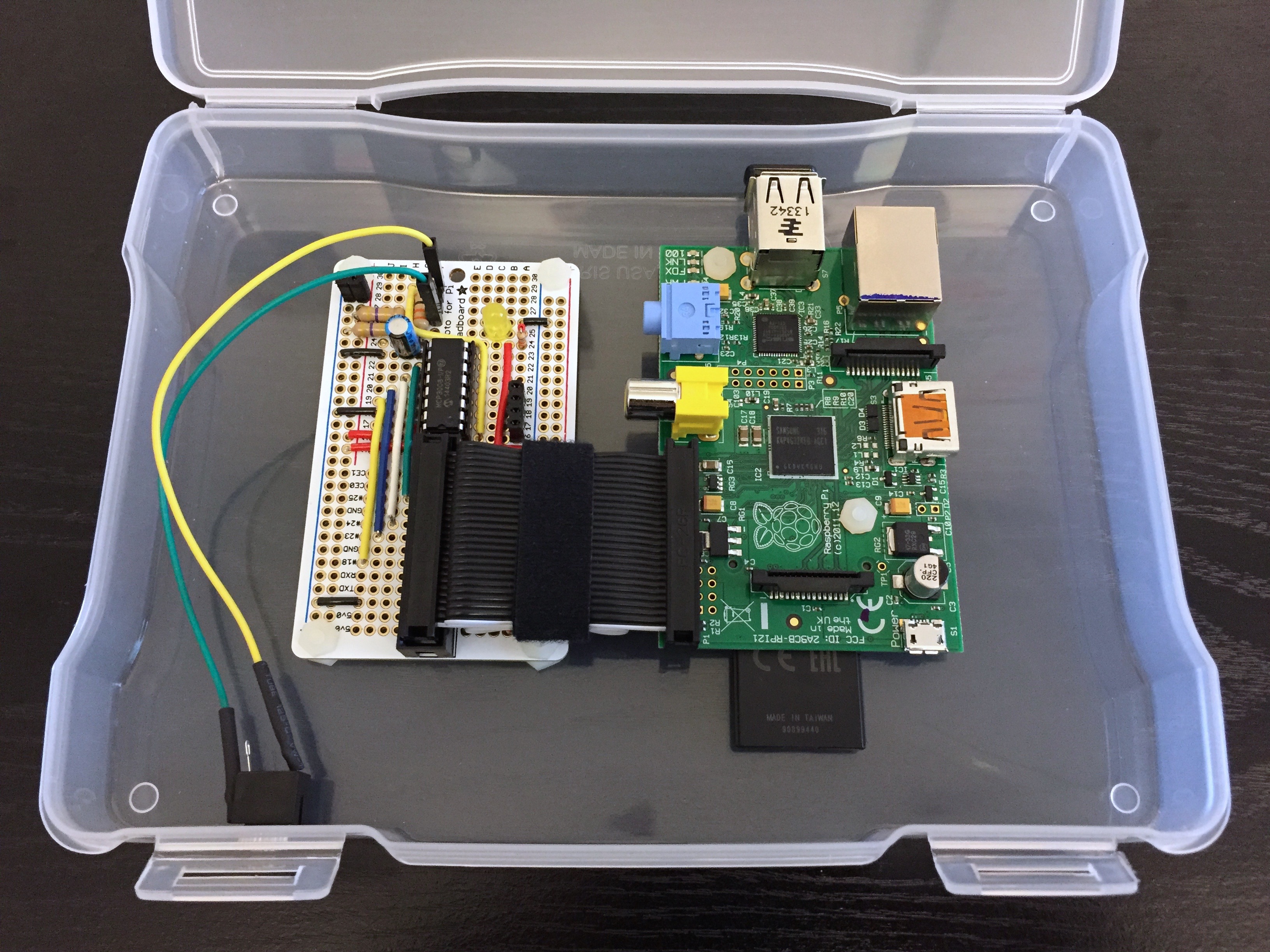
We also use Slack for team chat and various notifications, so integrating the coffee machine status was a no-brainer. Using a non-invasive/inductive current sensor and Raspberry Pi, the following setup monitors coffee machine energy consumption and waits for a significant rise in current draw, followed by several minutes of sustained usage. Once a time threshold has passed, it does an HTTP POST to a Slack webhook, sleeps for about 15 minutes, then starts monitoring again. This “brewbot” code is available on GitHub, and a parts list can be found below.

Completed kit

Packaged in box

ADC board

Full parts list:

Related reading: Hyper Text Coffee Pot Control Protocol

GottaGo

July 23, 2013

Working at Blackboard Mobile making unique mobile apps is fun, but occasionally it’s interesting to do something completely different at work, just to see what you can come up with. To that end, we recently hosted our first Hackathon, where small teams of co-workers had 24 straight hours to create a project of any theme using resources available inside our outside of the office, and the results would be judged by our peers. One of the other benefits of working in a growing industry is that we’re expanding our staff almost weekly. Unfortunately, though, that means that the building we’re in is less and less able to handle the increasing capacity. Specifically, the bathrooms are occupied more frequently, resulting in either a return trip to your desk only to try again later, or an awkward wait of unknown duration.

header

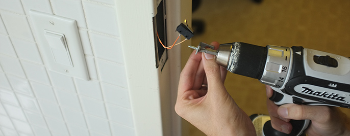
Working with Joe Taylor and Eric Littlejohn, our Hackathon project set out to make the office bathroom availability more visible and accessible through a combination of hardware and software. The piece of the project that lets this all work is a microswitch installed inside each door jamb, such that when the locking bolt is engaged, the switch is tripped. That way, we can do anything with resulting data, knowing that when the door is locked, the room is in use. Running wire down through the hollow metal trim was tedious and time consuming, and involved a lot of false starts and fishing around with a straightened coat hanger, but we finally got a run of wire inside each frame.

door switch

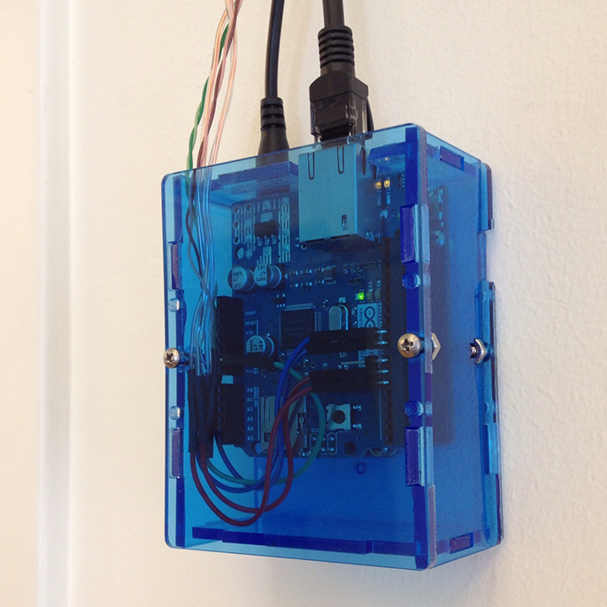
On each office floor there are two bathrooms side by side, and the pair of switches inside the door jambs are wired to a single Arduino fitted with an Ethernet Shield for network connectivity. The Arduino samples the switches many times per second, providing near-instant feedback.

arduinno board

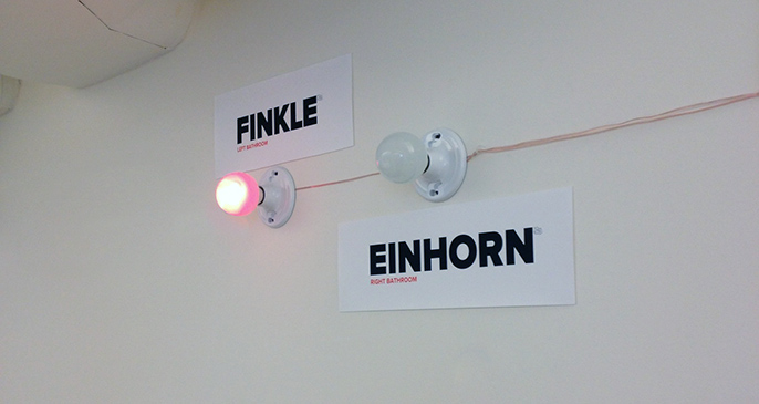
After debouncing the switch input signal over about 50 milliseconds, the Arduino waits for a definitive change in state – from locked to unlocked, or unlocked to locked – before illuminating LED lights on the wall.

wall lights

After the light corresponding to the now-occupied bathroom is lit, the Arduino also performs an HTTP POST, sending the event details (floor level, which room, and current occupancy state) to an in-house webserver running Node.js and MongoDB. The webserver records the data and makes it visible on a web page for viewers to check the availability digitally, for those who can’t see the wall mounted lights from their seating position.

event sequence animation

If you’d like to employ a project like this, the code we hacked together is available on GitHub, and the wiring is rather straightforward:

  • All components share a common ground
  • LED anodes are wired to room_a_led_pin and room_b_led_pin and brought high when doors are locked, and low when unlocked
  • Switches bring room_a_switch_pin and room_b_switch_pin low when triggered, and the Arduino uses the INPUT_PULLUP pinMode for the unlocked state

Our Hackathon project came in at second place, losing to an as-yet-unannounced software project, but we had a lot of fun staying up and hacking all night!

Adventures with Nest

June 6, 2013

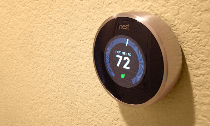
I recently purchased a pair of Nest Learning Thermostats for my new home. Compared to the white brick style Honeywell thermostats that came with the place, the Nest is so much more advanced. It does temperature learning, auto-away, and remote control over Wi-Fi from the web and iOS devices. It also has a color LCD and just generally looks beautiful on the wall with its brushed stainless steel housing.

nest thermostat

Installing the Nest is pretty straightforward with a modern forced air heating and cooling system:

  • Remove the old thermostat and mounting plate from the wall
  • Disconnect the wires
  • Patch and paint any holes
  • Install the Nest mounting base and connect the wires
  • Pop the Nest onto the base and configure the software

My initial install went well physically, but not long after, I discovered that the Nest would regularly run out of battery power. I quickly learned that due to how the HVAC circuits are arranged, the Nest can only draw power while the system is running. When the system is not busy heating, cooling, or running the fan, the Nest is left to run under its own battery power. And in sunny California during the springtime, the system doesn’t run often enough to let the Nest keep a charge. Several times per day, I would have to unplug the Nest from its base and charge it over micro USB. Not a great solution.

Reading more about the Nest and HVAC circuitry, I found that there is a solution for situations like this. A “common wire” that provides a path back to the HVAC controller would allow the Nest to draw the power it needs while not running any systems. As luck would have it, my system provided this common wire, but connecting it to the Nest had no effect on the battery. More telling was the fact that the Nest did not detect that the wire was connected.

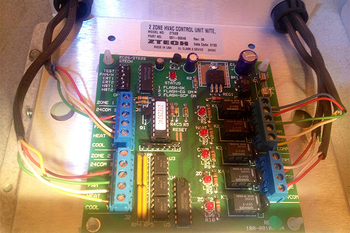
So, I decided to find out what was at the other end of that common wire. I put up a ladder and ventured into the attic of my home and scouted around the furnace. On top of it, inside an easily-opened metal enclosure, was the thermostat controller, a ZTech ZTE2S. Double checking the wiring diagram and comparing it with the wires on the left (coming from the Nests), it’s clear that the blue common wire is simply not connected to the controller. In the photo below, you can see that it’s clipped short, close to the brown jacket covering the bundle of five wires.

wiring before with blue wire disconnected

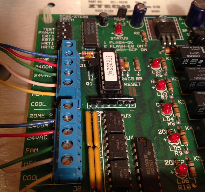
Reconnecting the wire was a matter of disconnecting the wires that were already connected, snipping them all to the same length, and stripping a little plastic off the end so that all five can be connected to the HVAC controller.

wiring after with blue wire connected

A few hours after leaving the Nest installed with the common wire attached and the HVAC controller all closed up, its battery has fully charged and the features work great.

Mastodon